HELLO MY
FRIENDS,
Download Autocad drawing of the
200 housing civil
engineering
trades which contains:
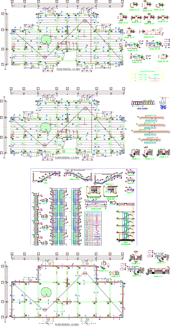
Infrastructure; foundations plan, bracing
sailing sole cases,
peripheral sailing, panel shaping steels, classification footings,
formwork reinforcement
foundations
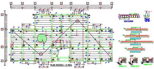
Superstructure; formwork floors, details
of formwork,
prefabricated girder-type
PML, details floor,
table of hats,
formwork
and reinforcement poles sails, formwork
reinforcement stairs, table of shaping steels, formwork
reinforcement chaining,formwork reinforcement beams.
DESCRIPTION
Execution mode of earthworks:
 1-The term "excavation" means any work
involving the movement of land resulting from cuts and fills, and whose purpose is to make good platforms for
building later leveled
the building.
1-The term "excavation" means any work
involving the movement of land resulting from cuts and fills, and whose purpose is to make good platforms for
building later leveled
the building.2-The earthworks are for all types of land liable to be encountered, including rock solid or cracked, clay, soil instability ... and so. They also agree to all depths specified in the bill of quantities.
Ways of making excavations in
foundation:
 1 - Excavation of foundation
work of all the books, they are
for all kinds of soils including rock
and will be executed
at the prescribed depth in the
plan or agreed by mutual
agreement running.
1 - Excavation of foundation
work of all the books, they are
for all kinds of soils including rock
and will be executed
at the prescribed depth in the
plan or agreed by mutual
agreement running.2 - The excavations will be performed by trench as for retaining walls and solely and necessarily per well insulated footings of the building (according to plans).
3 - The bottom of excavations shall be kept dry during the execution of foundations and every precaution must be taken to prevent landslides and rockfalls land in the wells.
4 - The earthworks for raft will be executed with a shovel or bulldozer, designated to the coast. Accurate leveling will be done, the bottom of excavations shall be approved jointly by the contractor, the consulting engineer and technique control of construction.
Formwork:
The forms present sufficient rigidity to resist deformation and sensitive
to shocks to which they are incurred during the execution of works and taking
into account the forces generated by the drying of concrete.
They shall be sufficiently tight to prevent loss of milt during the implementation and vibration of concrete. The Contractor shall scrape and clean and lubricate the casing, remove the nails from the boards before using it again and water them well before pouring concrete.
Was the formwork must be arranged so that they do on the bearing surfaces below that efforts compatible with such strength and in particular they cause no deformation or depression, which consequently lead to a deformation of the formwork. The number of supports and surfaces bearing sole plates will be determined accordingly.
The Contractor shall perform the bracing shuttering and effective for their support to prevent buckling and spill. The removal of the forms shall be gradual and without shock and efforts by purely static.
It will begin when the concrete formwork will have acquired sufficient hardening to withstand the stresses to which it will be submitted immediately after, without subsequent deformation and the security sufficient.
The normal time for stripping are indicative as follows: (Refer to the opinion of the consulting engineer)
 a) - Traditional
formwork:
a) - Traditional
formwork:- Pillars 03 days
- Slab 14 days
- Beams 20 days
b) - Tunnel Formwork:
- 48 hours under normal conditions
- 24 hours with proper use of adjuvant.
Execution and installation of reinforcement:
1 - The Contractor shall not implement frames after verification of the formwork is contradictory with the consulting engineer. The bars shall be strictly diameters and shall be provided according to plan. The minimum distance from the walls of the shuttering frames of 2.5 cm depending plan reinforced concrete. The permissible deviation in the position of each frame will not exceed half of its diameter and shall in no case exceed 1cm.
2 - where bending of the bars is provided, and will never hot mechanically, using mandrels or by another method for obtaining the indicated radii of curvature or admitted and a regular curvature of the armature . Outside of curves, the bars must be perfectly straight, welding two bars between them is strictly prohibited.
3 - The bars are secured and connected together by ligaments to son iron at any point of meeting and at any point indicated, to prevent their displacement during the pouring, tamping or vibrating the concrete.
4 - All bars placed in the upper parts of the slabs (in the false doors or other) will be maintained at the required level by using metal supports, the latter must be sufficiently rigid, stable and secured to the plates to prevent movement deformation of it both before and during the implementation of concrete.
5 - The longitudinal bars in concrete structures will be straightened and held parallel to the formwork and parallel to each other.
6 - Senior, brackets and frames connecting pins, will be stretched so that the system becomes dimensionally stable.
are indicated radii of curvature or admitted and a regular curvature of the frame. Outside of curves, the bars must be perfectly straight, welding two bars between them is strictly prohibited.
3 - The bars are secured and connected together by ligaments to son iron at any point of meeting and at any point indicated, to prevent their displacement during the pouring, tamping or vibrating the concrete.
4 - All bars placed in the upper parts of the slabs (in the false doors or other) will be maintained at the required level by using metal supports, the latter must be sufficiently rigid, stable and secured to the plates to prevent movement deformation of it both before and during the implementation of concrete.
5 - The longitudinal bars in concrete structures will be straightened and held parallel to the formwork and parallel to each other.
6 - Senior, brackets and frames connecting pins, will be stretched so that the system becomes dimensionally stable.
INFO ABOUT THE UPLOAD
Format : .zip
File Type: Autocad 2004
File Size: 3.65 Mo
Category: HABITAT CIVIL ENGINEERING
Language: French
Date Submitted: 14/10/2011
Copyright © terms of use for 200 SOCIAL HOUSING, CIVIL ENGINEERING, (.dwg).
You can use this project on your own site for purposes recommendation and education by placing one of the links below.
You can use this project on your own site for purposes recommendation and education by placing one of the links below.
Link HTML
PermaLink URL
Link BB code


